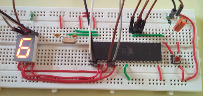
8051 Program For Seven Segment Display
7 Segment display Interfacing with 8051 Microcontroller. Interfacing a 8051 microcontroller with a 7 segment Common. Mohan Power Electronics Ebook. Program to display '0' on the seven segment. 7 segment display interfacing with 8051 microcontroller (AT89C51). This 8051 Microcontroller based seven segment display interface.


Implementing a 4-bit counter using an 8051 and. An 8051 chip. The program will be used. Interfaced to the 8051 chip. For the seven segment display we will. Decimal Counter Using Two 7-segment displays and an 8051. And the 7-segment displays need to be wired to the. Used to burn your program unto the 8051 chip.
• What is SEVEN SEGMENT DISPLAY (SSD)? – A seven segment display is a form of electronic display device for displaying decimal numbers (and some alphabets too). SSD may use a liquid crystal display (LCD), a light-emitting diode (LED) for each segment, or other light-generating or controlling techniques such as cold cathode gas discharge, vacuum fluorescent, incandescent filaments, and other.
• Types of SSD– There are mainly two types of SSD available. In a simple LED package, typically all of the cathodes (negative terminals) or all of the anodes (positive terminals) of the segment LEDs are connected and brought out to a common pin; this is referred to as a “common cathode” or “common anode” device. Besides this, there is also a SSD multiplexer is used called 2 digit, 3 digit and so on as you can see on photos. • Operation – In a simple common cathode LED package SSD, there has 10 pin out of which 2 is ground and rest is LED segments. Particular LED segment is glow(ON) by giving logic ‘1’ to it and rests at logic ‘0’.
So we need to program this 8 pin to display our number on SSD. In following table, we convert this 8 pin’s in 8 bit binary data and then that data into hex number and shows the hex number of displaying digits below.
• The 7 segment display is found in many displays such as microwaves or fancy toaster ovens and occasionally in non cooking devices. It is just 7 LEDs that have been combined into one case to make a convenient device for displaying numbers and some letters. The display is shown on the left.
The pin out of the display is on the right. This version is a common anode version. That means that the positive leg of each LED is connected to a common point which is pin 3 in this case. Neff Double Oven Installation Instructions. Each LED has a negative leg that is connected to one of the pins of the device. To make it work you need to connect pin 3 to 5 volts.
Then to make each segment light up, connect the ground pin for that led to ground. A resistor is required to limit the current. Rather than using a resistor from each LED to ground, you can just use one resistor from Vcc to pin 3 to limit the current.
The following table shows how to form the numbers 0 to 9 and the letters A, b, C, d, E, and F. '0' means that pin is connected to ground. '1' means that pin is connected to Vcc. Now, we want to run the display with the AT89C51 microcontroller. We will use Port 0 to run the display. Connect the AT89C51 to the 7 segment display as follows. Program to display '0' on the seven segment display.